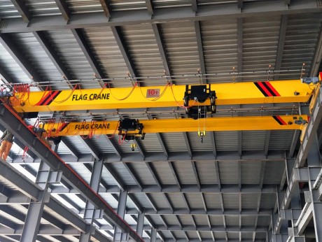
1. First installation of overhead traveling crane
- 1. First, according to the span size of the crane customized by the user, or according to the span size measured by our company after installing the rails for the customer, move the trolley on the welding fixture to confirm the span. When s<10m, the gauge tolerance is controlled by Δs≤±3mm; when s>10m, the gauge tolerance is controlled by Δs≤±[3+0.25×(s-10)]mm. The top surfaces of the two rails on the trolley should be in the same position of one layer, and the two rails are parallel. The data should be recorded during the installation of the overhead traveling crane.
- 2. Place the two beams on the rail so that the distance between the connecting plates of the two beams is 5-6mm larger than the distance between the connecting plates at both ends of the main beam. Control the diagonal difference of the wheel centerline measured from the a, B, C, and D reference points |E1-E2|≤5mm, and control the centerline of the two beams (i.e. the centerline of the connecting plate) to be in the same vertical plane.
- 3. Use m275 to connect the two ends of the main beam to the main beam, and use m275 or hanging card to weld the baffles at both ends of the main beam.
2. Installation of rails before installation of overhead traveling crane
- 1. Labor organization: The installation team is generally composed of 5 people, including skilled mechanical installation and assembly workers. The installation team leader formulates the work plan and arranges it in a unified manner.
- 2. Before installation, check whether the attached channels, scaffolding, ladders, lifting wire ropes, and hand winches are safe, firm, and reliable, and cut off the power supply lines that may hinder safety and risks.
- 3. Safety helmets and safety belts must be hung when installing overhead traveling cranes. It is strictly forbidden to work without shoes or slippers, and tighten the shoelaces.
- 4. Remove sand, stone, cement slag and other debris on the cement beams supporting the rail.
- 5. The type of rails on the same rail should be the same. There should be no cracks or scars on the surface of the rails, and the rails should be corrected in advance when they are bent.
- 6. The rail is hoisted onto the rail by the loading and unloading group.
- 7. When installing a overhead traveling crane, fitters should pad the support points of the rail with pads, and the joints should not be left hanging. Tighten the nuts with a plum wrench or a special closed hexagonal wrench.
- 8. Rail installation should meet the following requirements:
(1) rail gauge tolerance: When s≤10, Δs=±3mm; when s>10, Δs=±[3+0.25×(s-10)]mm.
(2) The limit error of the rail top surface relative to the theoretical height is ±10mm, but the maximum value does not exceed ±15mm. The maximum height difference between the two rails is 10mm. The curvature along the length direction in the vertical plane should not be greater than 2mm for every 2m of measured length.
(3) Within the total length of the rail, the lateral limit error is ±10mm. When the horizontal plane is curved along the length direction, the limit error within every 2m of measured length should not exceed ±1mm.
(4) The rail joints should be aligned.
(5) The error between the center of the rail and the center of the web of the rail beam shall not exceed half the thickness of the web of the rail beam.
(6) The error between the top surface of the rail and the theoretical position should not exceed the length direction: TGβ≤0.003; transverse direction: TGβ≤0.005.
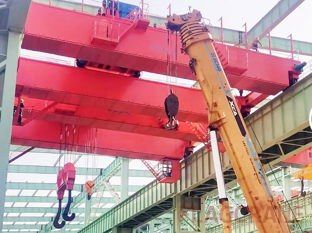
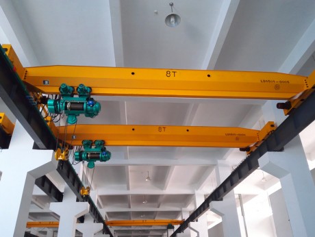
3. Lifting of overhead traveling cranes
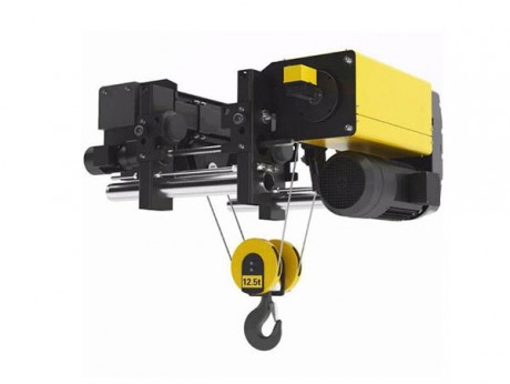
The overhead traveling crane (not equipped with electric hoist) is unloaded at the user's equipment site, and the electric hoist is installed by the assembler. When installing the electric trolley and the two-wheel trolley, the adjustment pad should be installed on the bolts between the two wall panels according to the width of the I-beam rail to ensure that the gap between the side surface of the lower fender of the I-beam and the edge of the wheels on both sides is 3-5mm. After adjustment, the electric hoist is fixed to the midpoint of the main beam with a rope.
Professional lifting personnel use the structure of the other workshop for lifting or use the mast for lifting. Lift the tread of the end beam of the overhead crane to 30mm from the top of the rail. The crane slowly descends and moves left and right to align the center line of the four-wheel tread with the center line of the rail.
- 1). Use the roof beam as the fulcrum
Use the factory building's own structure to lift the overhead traveling crane. In this case, the lifting plan should be formulated according to the structural characteristics of the factory building. Considering the most unfavorable conditions for lifting, the structural stress of the plant is calculated. This plan can only be selected when the structure of the workshop can withstand these weights. (Or it can be selected with the consent of the contractor).
- 2). Mast beam crane
First, select the derrick and calculate its strength and stability, and calculate the strength of the wire rope and other available lifting equipment. This method (pulley block or hand winch) is used for lifting cranes. The mast beam can be set outside the crane, and the mast beam is slightly tilted. When the crane is lowered, it should be kept horizontal.
4. On-site equipment commissioning of overhead traveling cranes
- 1. The driving equipment of the trolley running mechanism is installed on the end beam.
- 2. The main beam is connected by bolts (the bolts are special bolts). After the main beam is assembled, it is inspected according to the relevant requirements of JB/t1306-94. (Before the main beam is connected with the end beam, the welding process position of the positioning reference connection plate should be determined on the tire frame), and the burrs should be removed before installation.
- 3. Assemble the terminal travel switch and other electrical equipment of the crane on the beam, connect the relevant electrical components, and debug the conical motors at both ends to make the crane motors in the same direction. When power is turned on, be sure to jog first.
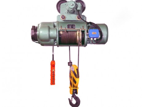
- 4. The electric hoist of the overhead traveling crane can be installed on the main beam first, and then erected on the rail together with the crane, or it can be installed separately.
- 5. Refer to the wiring diagram of the electrical equipment and set up the electric busbar.
- 6. All circuits should be installed according to the electrical schematic diagram. After installation, the operating direction of the crane must be consistent with the prescribed direction.
- 7. The user sets the block and safety ruler.
- 8. Install the wire bracket on the main beam.
- 9. Adjust the motor brake spring and adjust the trolley brake. Remove the fan cover 7, loosen the screw 6, tighten the adjustment nut 5, loosen one and a half turns or tighten one and a half turns, and then fix the adjustment nut 5.
- Note: Tighten the adjustment nut 5 clockwise to adjust the motor brake, otherwise it is to loosen. It is necessary to adjust to balance the braking of the motors on both sides.
5. Trial operation of overhead traveling crane
Newly installed cranes must pass the test and be powered on before they are officially used.
- 1. No-load test
Start the motors of each mechanism without load for forward and reverse test to check whether the direction of the control line is correct, the lifting and lowering of the hook, the front and rear running direction of the trolley, and the left and right running direction of the trolley are consistent with the direction indicated by the control button. The test time is not less than 5 minutes.
- 2. Static load test
Before the test, the empty car should be parked at the end of the main beam, and the reference point for measuring the deflection of the main beam should be determined in the middle of the span. Drive the trolley to the middle of the main beam span, lift the test load of 1.25gn, and place it at a height of 100-200mm from the ground. The suspension time is not less than 10 minutes. After unloading the car, drive the trolley to the end of the main beam to check whether the main beam is deformed. Repeat three times. The main beam is allowed to have a small deformation in the first and second times. The main beam should not be deformed in the third time. Check whether the main beam has a pre-camber of not less than 0.8s/1000. After the static load test, the crane's various parts shall not have quality problems such as deformation, cracks, paint peeling, loose joints or damage.
- 3. Dynamic load test
The dynamic load test of each part of the crane should be carried out separately first, and then the joint effect test should be carried out. The two parts should be started at the same time. The test load is 1.1gn. According to the corresponding operating level of the crane, each action should be reversed within the entire operating range. According to its operating cycle, the test time should be 1h. If each component completes its functional test and no looseness or damage is found in the subsequent visual inspection, the test is considered qualified. Braking distance of the operating mechanism (unit: m) crane ≤0.1V (V trolley operating speed); trolley ≤0.06v (trolley operating speed); lifting mechanism lowering braking distance (unit: m) ≤V/100 (crane lifting speed).