0086-18695891045
Time : 2024-08-05
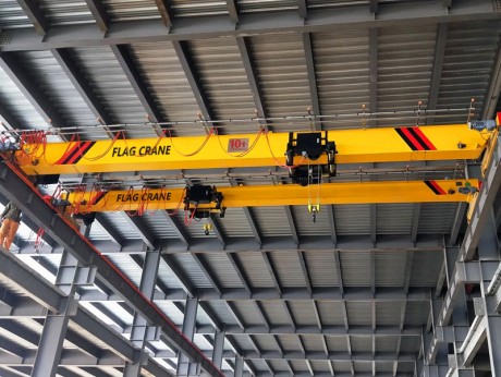
In the construction of power plants, overhead crane are a widely used lifting machinery. They are frequently used, have a large workload and large vibrations, so the failure rate is high, which brings many adverse effects to the construction. During the electrical installation and commissioning of overhead crane, scientific and reasonable construction methods are the key to ensuring the quality of installation. The installation of electrical equipment and the laying of wires of overhead crane should be carried out strictly in accordance with the attached electrical schematics, wiring diagrams, electrical equipment general diagrams and corresponding specifications.
Before the electrical installation of overhead crane, you should be familiar with the relevant electrical diagrams and technical conditions in detail, understand the interaction and operation principles of each component, so as to quickly deal with problems that occur during installation and commissioning. All electrical equipment and components should be cleaned and checked before installation. All electrical equipment and components should be free of defects, should operate flexibly, and should not be stuck or loose. The models, specifications, and closing order of contacts of electrical equipment and components must comply with the drawings.
1.1. Motor
First, make a general appearance inspection, turn the coupling to observe whether the rotor rotates flexibly, and use a megohmmeter to measure its insulation resistance. If the stator is greater than 1.5 megohms and the rotor is greater than 0.8 megohms, it can be used, otherwise it should be dried. The drying method can be placed in an oven or a low-voltage short-circuit current can be passed.
1.2. Electromagnet
During installation, check whether its moving parts are loose, skewed or stuck, and remove rust and other dirt from the contact surface between its moving parts and the magnet. When the magnet is working, there should be no gap between its contact surfaces. If there is, it must be adjusted to remove the gap.
1.3. Linkage console or controller
The joint surface of each contact should be line contact, and the pressure is about 10 to 17 Newtons depending on the size of the contact, which is adjusted by the nut of the compression spring. Each wiring screw should be tightened and the contact should be good. The operating handle should be flexible and the gear position should be obvious.
1.4. Resistors
The resistor wiring must be correctly connected according to the information provided. If the motor is found to be insufficient, the control handle cannot lift the rated load or start the large and small vehicles in the specified position. First, check whether the resistor wiring is wrong. For the mechanism driven by two motors, the resistor used should be appropriately selected and adjusted. Resistors with larger resistance values are used for motors closer to the control room, or for motors with a slip tolerance of "-".
Resistors with four boxes or less can be directly stacked together. Resistors with more than four boxes are best installed on the resistor rack, with a distance of 80 mm between each box, and a heat insulation board can be added in the middle to reduce the temperature rise of the uppermost resistor.
The layout of the resistor rack should take into account the convenience of maintenance and replacement of resistor elements, which is conducive to heat dissipation. The channel in front of the rack should be no less than 600 mm, and the distance between the resistor element and the wall and floor should be no less than 150 mm.
The resistor should be placed in a direction parallel to the main beam, and the resistor rack should be firmly installed and overlapped on the large tie rod of the walkway as much as possible to reduce the vibration generated during the operation of the crane. If necessary, a pull plate can be added to the upper end of the rack, and one end of the pull plate can be welded to the steel structure. ,
Before installation, the components and electrical circuits in the maintenance box and control box should be carefully checked. The components must not be damaged, especially the arc extinguishing cover and auxiliary contacts of the contactor. The insulation resistance of the line should meet the requirements of relevant regulations. Check whether the action of each time relay meets the setting value required by the product's factory technical documents.
The setting value of the time relay of the lifting control box: 1SJ is 0.6 seconds, 2SJ is 0.2 seconds, 3SJ is 0.6 seconds, and 4SJ is 0.3 seconds. The channel in front of the control is not less than 600 mm. The control box should be installed firmly and reliably to minimize the vibration during the operation of the crane. If necessary, support can be added. The deviation between the screen and the vertical surface shall not exceed 5 degrees.
The limit switch is an important device to ensure that there are no major equipment and personal accidents during the operation of the crane. Before installation, the switch should be carefully checked to see if it is flexible and reliable. After installation, they should be adjusted one by one. The distance between the limit switch and the impact ruler of the trolley and the trolley should be adjusted appropriately. Too tight will damage the switch and have no protective effect. The two limit switches of the lifting mechanism should be adjusted separately. When the hook reaches the limit height, the heavy hammer limit switch is disconnected first, and the rotary limit switch can be disconnected at a higher position, but the limit height should not be exceeded at this time.
The working surface of the conductive slide must be lubricated and clean, and the insulator of the trolley conductor must be intact and free of cracks, and must be reliably fixed on the conductive frame. The conductor must be pressed tightly against the conductive sliding wire. If sparks occur during operation, it means that the contact is poor. The reason may be that the conductor and the conductive sliding wire are not in close contact or the working surface is not clean, or both.
Usually, in order to ensure safety, the operating room is generally installed on the opposite side of the trolley conductive sliding wire. If it is necessary to install it on the same side, a protective net should be added for protection.
When the ambient temperature of the crane is -25~45℃, the cable is CFR type marine rubber insulated chloroprene sheathed soft cable. The maximum temperature is greater than 50℃, and the cable is CEFR type marine EPDM rubber insulated heat-resistant chloroprene sheathed soft cable. When the minimum temperature is -25℃, the cable is YHD type rubber insulated cold-resistant rubber sheathed cable.
When installing, the cable should be straightened out first, the torque should be eliminated, and it should be arranged on the end clamp, cable pulley and drag pulley in sequence according to the requirements of the drawing. Push the trolley to the extreme position away from the operating room, release the cable, adjust the position of the cable trailer, make the length of each cable section basically the same and maintain a certain degree of sag, and keep the droop angle at about 120°. After adjustment, use the cable clamp to firmly fix the cable to the end clamp and the drag pulley, and then push the trolley to the extreme position near the operating room, adjust the cable, make the suspension length of each cable section basically the same, and use the cable clamp to firmly fix the cable to the cable pulley. The cable is braided and clamped with iron sheets every 500 to 700 mm.
After the wires and wire pipes are laid, consider the safety grounding problem. The outer shell of all live parts of the crane should be reliably grounded to avoid accidental electric shock accidents. When the trolley rails are not welded to the main beam, welding grounding should also be adopted, and the lighting transformer should be grounded on the low-voltage side according to the drawings.
The grounding wire should be made of galvanized flat iron with a cross-section of not less than 75 square millimeters, 10 square millimeters bare copper wire or 30 square millimeters galvanized round steel. The grounding connection between the operating room and the crane body should be made of 4×10 mm galvanized flat iron, and there should be no less than two connections. The grounding wire should be fixed by electric welding, or the grounding screw (galvanized) on the equipment should be used. Rust stains should be removed from the joints, and the grounding wire should be painted black. The grounding resistance between any point on the crane and the neutral point of the power supply should not be greater than 4 ohms. A fuse should be installed on the crane or at the beginning of the power supply slide, and the rated current of the fusible link should be 0.63 times the maximum current of the crane or the power supply slide.